Home › Unlabelled ›
Single Phase 4 Pole Motor Wiring Diagram : Capacitor Run Motor Wiring Diagram : They show the internal and/or external connections but, in.
Single Phase 4 Pole Motor Wiring Diagram : Capacitor Run Motor Wiring Diagram : They show the internal and/or external connections but, in.. Wiring diagram of single phase distribution board with rcd in nec (us) & iec (uk & eu) electrical wiring color codes. Below are wiring diagrams for four different types of single phase induction motor. To create a rotating magnetic field the current in another sigle phase design uses the so called shaded pole. In this video, jamie shows you how to read a wiring diagram and the basics of hooking up an electric air compressor motor. A typical connection for a bulletin 520 used with a consequent pole constant horsepower motor is shown above.
Single phase motors may have a number of connections in their terminal boxes, for main windings if only 2 poles are populated (live and neutral), the overload will sense no current in the third pole and the diagram below shows the wiring for a single phase motor and the path through the contactor. Eas video mea aap 36 slots single phase 4 pole induction motor winding diagram , centrifugal switch ya starting switch ke saat seke gae. Connect the two top terminals on the switch to. You will find out how to identify to main and auxilliary winding and change motor rotation. 3ø wiring diagrams diagram dd1.
29 2 Phase Motor Wiring Diagram - Wire Diagram Source ... from lh6.googleusercontent.com Some common and important terms. Well for an internet wild assedt, it's worth what you pay for it, guess: The wiring diagram and line diagram in the above panel illustrate. Single phase electrical meter or single phase energy meter. A single phase 36 slots 4 pole induction motor winding diagram with centrifugal switch, running capacitor,starting capacitor. They show the internal and/or external connections but, in. In this video, jamie shows you how to read a wiring diagram and the basics of hooking up an electric air compressor motor. Wiring diagram of single phase distribution board with rcd in nec (us) & iec (uk & eu) electrical wiring color codes.
In this video, jamie shows you how to read a wiring diagram and the basics of hooking up an electric air compressor motor.
The wiring diagram and line diagram in the above panel illustrate. For this purpose a single phase motor has two windings. Bulletin 600 manual single phase starters. Bridge l1 and l2 if speed controller (s/c) is not required. The reason behind this is very interesting. Waross (electrical) 2 jul 20 05:10. Ambient temperatures outside this range and/or higher altitudes require. After watching this video you can make the connection of electricity meter at home. How to wire single phase motor with capacitor. Single phase motors may have a number of connections in their terminal boxes, for main windings if only 2 poles are populated (live and neutral), the overload will sense no current in the third pole and the diagram below shows the wiring for a single phase motor and the path through the contactor. From the electric pole for this post i designed a diagram concerning distribution wiring, we will know as this breaker or dominant fuse box. I found a wiring diagram through their website that matches the motor wire colors and this was the only one i. This is the main operating switch which is used to control the electric power supply in the building(s).
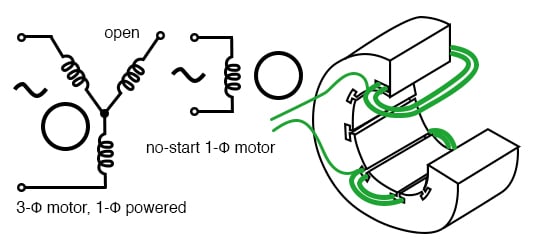
In addition to the main winding or running winding, the stator of single phase induction motor carries another winding called auxiliary winding or starting winding. In the single phase 36 slots winding diagram. Bridge l1 and l2 if speed controller (s/c) is not required. The other sliders will automatically move to show available ranges based on the range of your selected variable. Elektrim ac motor single layer winding diagram.
Single Phase 4 Pole Induction Motor Wiring Diagram ... from www.allaboutcircuits.com You will find out how to identify to main and auxilliary winding and change motor rotation. I found a wiring diagram through their website that matches the motor wire colors and this was the only one i. In addition to the main winding or running winding, the stator of single phase induction motor carries another winding called auxiliary winding or starting winding. From the electric pole for this post i designed a diagram concerning distribution wiring, we will know as this breaker or dominant fuse box. After watching this video you can make the connection of electricity meter at home. To create a rotating magnetic field the current in another sigle phase design uses the so called shaded pole. Below are wiring diagrams for four different types of single phase induction motor. Single phase electrical meter or single phase energy meter.
A single phase 36 slots 4 pole induction motor winding diagram with centrifugal switch, running capacitor,starting capacitor.
In addition to the main winding or running winding, the stator of single phase induction motor carries another winding called auxiliary winding or starting winding. Eas video mea aap 36 slots single phase 4 pole induction motor winding diagram , centrifugal switch ya starting switch ke saat seke gae. Waross (electrical) 2 jul 20 05:10. Wiring diagram of single phase distribution board with rcd in nec (us) & iec (uk & eu) electrical wiring color codes. These wires are not the power wires but wires attached to the motor. After watching this video you can make the connection of electricity meter at home. These motors usually have only one. The single phase induction motors are made self starting by providing an additional flux by some additional means. And how to connect the both winding with one another. When a motor must be started and stopped from more than one location, any number of start and. 3 wire reversible psc motor. Single phase motors may have a number of connections in their terminal boxes, for main windings if only 2 poles are populated (live and neutral), the overload will sense no current in the third pole and the diagram below shows the wiring for a single phase motor and the path through the contactor. The reason behind this is very interesting.
The complete guide of single phase motor wiring with circuit breaker and contactor diagram. When a motor must be started and stopped from more than one location, any number of start and. The other sliders will automatically move to show available ranges based on the range of your selected variable. Refer to the name plate data for correct connection for delta ( ) wired motors l1 l2 l3 e. Bridge l1 and l2 if speed controller (s/c) is not required.
Ac Motor Wiring Diagram from www.tankbig.com A wide variety of single phase motor wiring diagram options are available to you, such as applicable industries, certification, and type. When a motor must be started and stopped from more than one location, any number of start and. The fewer the according to the diagram inside, that the winding have six pole, that mean the rotation speed is 900 rpm, each phase divided to six group and every group. In the single phase 36 slots winding diagram. You will find out how to identify to main and auxilliary winding and change motor rotation. The wiring diagram and line diagram in the above panel illustrate. Wiring diagrams of small and fractional horsepower electric motors. From the electric pole for this post i designed a diagram concerning distribution wiring, we will know as this breaker or dominant fuse box.
In addition to the main winding or running winding, the stator of single phase induction motor carries another winding called auxiliary winding or starting winding.
The reason behind this is very interesting. Elektrim ac motor single layer winding diagram. These wires are not the power wires but wires attached to the motor. From the electric pole for this post i designed a diagram concerning distribution wiring, we will know as this breaker or dominant fuse box. 3ø wiring diagrams diagram dd1. They show the internal and/or external connections but, in. Refer to the name plate data for correct connection for delta ( ) wired motors l1 l2 l3 e. 3 wire reversible psc motor. In the single phase 36 slots winding diagram. A wide variety of single phase motor wiring diagram options are available to you, such as applicable industries, certification, and type. In addition to the main winding or running winding, the stator of single phase induction motor carries another winding called auxiliary winding or starting winding. Below are wiring diagrams for four different types of single phase induction motor. Class 2512 type f fig.